by jhasensio

Month: December 2020

AVI for K8s Part 2: Installing AVI Kubernetes Operator

AVI Ingress Solution Elements

After setting up the AVI configuration now it’s time to move into the AVI Kubernetes Operator. AKO will communicate with AVI Controller using AKO and will realize for us the LoadBalancer and Ingress type services translating the desired state for this K8s services into AVI Virtual Services that will run in the external Service Engines. The AKO deployment consists of the following components:

  • The AVI Controller
    • Manages Lifecycle of Service Engines
    • Provides centralized Analytics
  • The Service Engines (SE)
    • Host the Virtual Services for K8s Ingress and LoadBalancer
    • Handles Virtual Services Data Plane
  • The Avi Kubernetes Operator
    • Provides Ingress-Controller capability within the K8s Cluster
    • Monitor ingress and loadbalancer K8s objects and translates into AVI configuration via API
    • Runs as a Pod in the K8S cluster

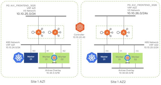
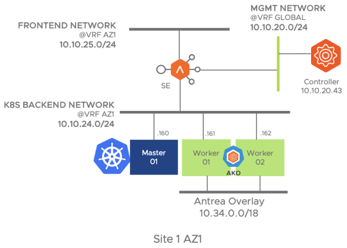
The following figure represent the network diagram for the different elements that made the AKO integration in the Site1 AZ1

Detailed network topology for Site1 AZ1

Similarly the below diagram represent the Availability Zone 2. As you can notice the AVI Controller (Control/Management Plane) is shared between both AZs in the same Site whereas the Date Plane (i.e Service Engines) remains separated in different VMs and isolated from a network perspective.

Detailed network topology for Site1 AZ2

I am using here a vanilla Kubernetes based on 1.18 release. Each cluster is made up by a single master and two worker nodes and we will use Antrea as CNI. Antrea is a cool kubernetes networking solution intended to be Kubernetes native. It operates at Layer3/4 to provide networking and security services for a Kubernetes cluster. You can find more information of Antrea and how to install it here. To install Antrea you need to assign a CIDR block to provide IP Addresses to the PODs. In my case I have selected two CIDR blocks as per the table below:

Cluster NamePOD CIDR BlockCNI# Master# Workers
site1-az110.34.0.0/18Antrea12
site1-az210.34.64.0/18Antrea12
Kubernetes Cluster CIDR block for POD networking

Before starting, the cluster must be in a Ready status. We can check the current status of our k8s cluster using kubectl commands. To be able to operate a kubernetes cluster using kubectl command line you need a kubeconfig file that contains the authentication credentials needed to gain access via API to the desired cluster. An easy way to gain access is jumping into the Master node and assuming a proper kubeconfig file is at $HOME/.kube/config, you can check the status of your kubernetes cluster nodes at Site1 AZ1 using kubectl as shown below.

kubectl get nodes
 NAME                     STATUS   ROLES    AGE   VERSION
 site1-az1-k8s-master01   Ready    master   29d   v1.18.10
 site1-az1-k8s-worker01   Ready    <none>   29d   v1.18.10
 site1-az1-k8s-worker02   Ready    <none>   29d   v1.18.10

In a similar way you can ssh to the master node at Site1 AZ2 cluster and check the status of that particular cluster.

kubectl get nodes
 NAME                     STATUS   ROLES    AGE   VERSION
 site1-az2-k8s-master01   Ready    master   29d   v1.18.10
 site1-az2-k8s-worker01   Ready    <none>   29d   v1.18.10
 site1-az2-k8s-worker02   Ready    <none>   29d   v1.18.10

Understanding pod reachability

As mentioned the Virtual Service hosted in the Service Engines will act as the frontend for exposing our K8s external services. On the other hand, we need to ensure that the Service Engines reach the pod networks to complete the Data Path. Generally the pod network is a non-routable network used internally to provide pod-to-pod connectivity and therefore is not reachable from the outside. As you can imagine, we have to find the way to allow external traffic to come in to accomplish the Load Balancing function.

One common way to do this is to use a k8s feature called NodePorts. NodePort exposes the service on each Node’s IP at a static port and you can connect to the NodePort service outside the cluster by requesting <NodeIP>:<NodePort>. This is a fixed port to a service and it is in the range of 30000–32767. With this feature you can contact any of the workers in the cluster using the allocated port in order to reach the desired deployment (application) behind that exposed service. Note that you use NodePort without knowing where (i.e. in which worker node) the Pods for that service are actually running.

Having in mind how a NodePort works, now let’s try to figure out how our AVI External Load Balance would work in an environment in which we use NodePort to expose our applications. Imagine a deployment like the one represented in the below picture. As you can see there are two sample deployments: hackazon and kuard. The hackazon one has just one pod replica whereas the kuard deployment has two replicas. The k8s scheduler service has decided to place the pods as represented in the figure. On the top of the diagram you can see how our external Service Engine would expose the corresponding virtual services in the FrontEnd Network and creates a Server Pool made up by each of the NodePort services, in that case, for the hackazon.avi.iberia.local virtual service a three member server pool would be created distributing traffic to 10.10.24.161:32222, 10.10.24.162:32222 and 10.10.24.163:32222. As you can see the traffic would be distributed evenly across the pool regardless the actual Pod is running at Worker 01. On the other hand since the NodePort is just an abstraction of the actual Deployment, as long as one Pod is up and running the NodePort would appear to be up from a health-check perspective. The same would happen with the kuard.avi.iberia.local virtual service.

As you can see, the previous approach cannot take into account how the actual PODs behind this exposed service are distributed across the k8s cluster and can lead into inefficient east-west traffic among K8s worker nodes and also, since we are exposing a service and not the actual endpoint (the POD) we cannot take advantage of some interesting features such as POD health-monitoring or what sometimes is a requirement: server persistence.

Although NodePort based node-reachability is still an option. The AKO integration proposes another much better integration that overcomes previous limitations. Since the worker nodes are able to forward IPv4 packets and because the CNI knows the IP Addressing range assigned to every K8s node we can predict the full range of IP Addresses the POD will take once created.

You can check the CIDR block that Antrea CNI solution has allocated to each of the Nodes in the cluster using kubectl describe

kubectl describe node site1-az1-k8s-worker01
 Name:               site1-az1-k8s-worker01
 Roles:              
 Labels:             beta.kubernetes.io/arch=amd64
                     beta.kubernetes.io/os=linux
                     kubernetes.io/arch=amd64
                     kubernetes.io/hostname=site1-az1-k8s-worker01
                     kubernetes.io/os=linux

 Addresses:
   InternalIP:  10.10.24.161
   Hostname:    site1-az1-k8s-worker01
< ... skipped output ... >
 PodCIDR:                      10.34.2.0/24
 PodCIDRs:                     10.34.2.0/24
< ... skipped output ... >

Another fancy way to get this info is by using json format. Using jq tool you can parse the output and get the info you need using a single-line command like this:

kubectl get nodes -o json | jq '[.items[] | {name: .metadata.name, podCIDRS: .spec.podCIDR, NodeIP: .status.addresses[0].address}]'
 [
   {
     "name": "site1-az1-k8s-master01",
     "podCIDRS": "10.34.0.0/24",
     "NodeIP": "10.10.24.160"
   },
   {
     "name": "site1-az1-k8s-worker01",
     "podCIDRS": "10.34.2.0/24",
     "NodeIP": "10.10.24.161"
   },
   {
     "name": "site1-az1-k8s-worker02",
     "podCIDRS": "10.34.1.0/24",
     "NodeIP": "10.10.24.162"
   }
 ]

To sum up, in order to achieve IP reachability to the podCIDR network the idea is to create a set of static routes using the NodeIP as next-hop to reach the assigned PodCIDR for every individual kubernetes node. Something like a route to 10.34.2.0/24 pointing to the next-hop 10.10.24.161 to reach PODs at site1-az1-k8s-worker01 and so on. Of course one of the AKO functions is to achieve this in a programatic way so this will be one of their first actions the AKO operator will perform at bootup.

AVI Kubernetes Operator (AKO) Installation

AKO will run as a pod on a dedicated namespace that we will create called avi-system. Currently the AKO is packaged as a Helm chart. Helm uses a packaging format for creating kubernetes objects called charts. A chart is a collection of files that describe a related set of Kubernetes resources. We need to install helm prior to deploy AKO.

There are different methods to install Helm. Since I am using ubuntu here I will use the snap package manager method which is the easiest.

sudo snap install helm --classic
 helm 3.4.1 from Snapcrafters installed

The next step is add the AVI AKO repository that include the AKO helm chart using into our local helm.

helm repo add ako https://projects.registry.vmware.com/chartrepo/ako "ako" has been added to your repositories

Now we can search the available helm charts at the repository just added before as shown below.

helm search repo
NAME                    CHART VERSION   APP VERSION     DESCRIPTION
ako/ako                 1.4.2           1.4.2           A helm chart for AKO
ako/ako-operator        1.3.1           1.3.1           A Helm chart AKOO
ako/amko                1.4.1           1.4.1           A helm chart for AMKO

Next step is to create a new k8s namespace named avi-system in which we will place the AKO Pod.

kubectl create namespace avi-system
namespace/avi-system created

We have to pass some configuration to the AKO Pod. This is done by means of a values.yaml file in which we need to populate the corresponding configuration parameters that will allow AKO to communicate with AVI Controller among other things. The full list of values and description can be found here. You can get a default values.yaml file using following commands:

helm show values ako/ako --version 1.4.2 > values.yaml

Now open the values.yaml file and change the values as showed in below table to match with our particular environment in Site 1 AZ1 k8s cluster. You can find my values.yaml file I am using here just for reference.

ParameterValueDescription
AKOSettings.disableStaticRouteSyncfalseAllow the AKO to create static routes to achieve
POD network connectivity
AKOSettings.clusterNameS1-AZ1A descriptive name for the cluster. Controller will use
this value to prefix related Virtual Service objects
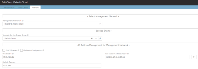
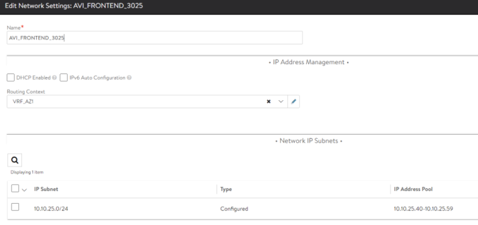
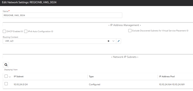
NetworkSettings.subnetIP10.10.25.0Network in which create the Virtual Service Objects at AVI SE. Must be in the same VRF as the backend network used to reach k8s nodes. It must be configured with a static pool or DHCP to allocate IP address automatically.
NetworkSettings.subnetPrefix24Mask lenght associated to the subnetIP for Virtual Service Objects at SE.
NetworkSettings.vipNetworkList:
networkName
AVI_FRONTEND_3025Name of the AVI Network object hat will be used to place the Virtual Service objects at AVI SE.
L4Settings.defaultDomainavi.iberia.localThis domain will be used to place the LoadBalancer service types in the AVI SEs.
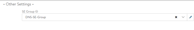
ControllerSettings.serviceEngineGroupNameS1-AZ1-SE-GroupName of the Service Engine Group that AVI Controller use to spin up the Service Engines
ControllerSettings.controllerVersion20.1.2Controller API version
ControllerSettings.controllerIP10.10.20.43IP Address of the AVI Controller
avicredentials.usernameadminUsername to get access to the AVI Controller
avicredentials.passwordpassword01Password to get access to the AVI Controller
values.yaml for AKO

Save the values.yaml in a local file and next step is to install the AKO component through helm. Add the version and the values.yaml as input parameters. We can do it that way:

helm install ako/ako --generate-name --version 1.4.2 -f values.yaml -n avi-system
 NAME: ako-1605611539
 LAST DEPLOYED: Tue Jun 06 12:12:20 2021
 NAMESPACE: avi-system
 STATUS: deployed
 REVISION: 1

We can list the deployed chart using helm CLI list command within the avi-system namespace

 helm list -n avi-system
 NAME              NAMESPACE   REVISION  STATUS      CHART       APP
 ako-1605611539    avi-system  1         deployed    ako-1.4.2   1.4.2

This chart will create all the k8s resources needed by AKO to perform its functions. The main resource is the pod. We can check the status of the AKO pod using kubectl commands.

kubectl get pods -n avi-system
NAME    READY   STATUS    RESTARTS   AGE
ako-0   1/1     Running   0          5m45s

In case we experience problems (e.g Status is stuck in ContainerCreating or Restars shows a large number of restarts) we can always use standard kubectl commands such as kubectl logs or kubectl describe pod for troubleshooting and debugging.

If we need to update the values.yaml we must delete and recreate the ako resources by means of helm. I have created a simple restart script that can be found here named ako-reload.sh that lists the existing ako helm deployed release, deletes it and recreates using the values.yaml file in the current directory. This is helpful to save some time and also to stay up to date with the last application version because it will update the AKO and choose the most recent version of ako component in the AKO repository. The values.yaml file must be in the same path to make it works.

#!/bin/bash
# Update helm repo f AKO version
helm repo add ako https://projects.registry.vmware.com/chartrepo/ako

helm repo update
# Get newest AKO APP Version
appVersion=$(helm search repo | grep ako/ako | grep -v operator | awk '{print $3}')

# Get Release number of current deployed chart
akoRelease=$(helm list -n avi-system | grep ako | awk '{print $1}')

# Delete existing helm release and install a new one
helm delete $akoRelease -n avi-system
helm install ako/ako --generate-name --version $appVersion -f values.yaml --namespace avi-system

Make the script executable and simply run it each time you want to refresh the AKO installation. If this is not the first time we execute the script note how the first message warn us that the repo we are adding was already added, just ignore it.

chmod +x ako_reload.sh
"ako" already exists with the same configuration, skipping
Hang tight while we grab the latest from your chart repositories...
...Successfully got an update from the "ako" chart repository
Update Complete. ⎈Happy Helming!⎈
release "ako-1622738990" uninstalled
NAME: ako-1623094629
LAST DEPLOYED: Mon Jun  7 19:37:11 2021
NAMESPACE: avi-system
STATUS: deployed
REVISION: 1

To verify that everything is running properly and that the communication with AVI controller has been successfully established we can check if the static routes in the VRF has been populated to attain required pod reachability as mentioned before. It is interesting to debug the AKO application using standard kubectl logs in order to see how the different events and API calls occur.

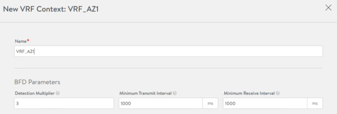
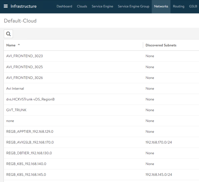
For example, we can see how in the first step AKO discovers the AVI Controller infrastructure and the type of cloud integration (vCenter). It also discovers VRF in which it has to create the routes to achieve Pod reachability. In this case the VRF is inferred from the properties of the selected AVI_FRONTEND_3025 network (remember this is the parameter NetworkSettings.VipNetworkList we have used in our values.yaml configuration file) at AVI Controller and correspondes to VRF_AZ1 as shown below:

kubectl logs -f ako-0 -n avi-system
INFO    cache/controller_obj_cache.go:2558      
Setting cloud vType: CLOUD_VCENTER
INFO   cache/controller_obj_cache.go:2686
Setting VRF VRF_AZ1 found from network AVI_FRONTEND_3025

A little bit down we can see how the AKO will create the static routes in the AVI Controller to obtain POD reachability in that way.

INFO   nodes/avi_vrf_translator.go:64  key: Node/site1-az1-k8s-worker02, Added vrf node VRF_AZ1
INFO   nodes/avi_vrf_translator.go:65  key: Node/site1-az1-k8s-worker02, Number of static routes 3

As you can guess, now the AVI GUI should reflect this configuration. If we go to Infrastructure > Routing > Static Routes we should see how three new routes has been created in the desired VRF to direct traffic towards the PodCIDR networks allocated to each node by the CNI. The backend IP address will be used as next-hop.

We will complete the AKO configuration for the second k8s cluster at a later stage since we will be focused on a single cluster for now. Once the reachability has been done, now it’s time to move into next level and start creating the k8s resources.

AVI for K8S Part 1: Preparing AVI Infrastructure

The very first step for start using NSX Advanced Load Balancer (a.k.a AVI Networks) is to prepare the infrastructure. The envisaged topology is represented in the figure below. I will simulate two K8S cluster environment that might represent two availability zones (AZ) in the same site. Strictly speaking an availability zone must be a unique physical location within a region equipped with independent power, cooling, and networking. For the sake of simplicity we will simulate that condition over a single vCenter Datacenter and under the very same physical infrastructure. I will focus in a single-region multi-AZ scenario that will evolve to a multi-region in subsequents part of this blog series.

Multi-AvailabilityZone Arquitecture for AVI AKO

AVI proposes a very modern Load Balancing architecture in which the Control plane (AVI Controller) is separated from the Data Plane (AVI Service Engines). The Data Plane is created on demand as you create Virtual Services. To spin up the Service Engines in an automated fashion, AVI Controllers uses a Cloud Provider entity that will provide the compute requirements to bring the Data Plane up. This architectural model in which the brain is centralized embraces very well VMware’s Virtual Cloud Network strategy around Modern Network Solutions: “any app , any platform, any device” that aims to extend universally the network services (load balancing in this case) to virtually anywhere regardless where our application exists and what cloud provider we are using.

Step 1: AVI Controller Installation

AVI Controller installation is quite straightforward. If you are using vSphere you just need the OVA file to install the Controller VM deploying it from vCenter client. Deploy a new VM deploying a OVF in the desired infrastructure.

AVI OVF Deployment

Complete all the steps with your particular requirements such as Cluster, Folder, Storage, Networks… etc. In the final step there is a Customize template to create some base configuration of the virtual machine. The minimum requirements for the AVI controllers are 8vCPU, 24 GB vRAM and 128 GB vHDD.

AVI OVF Customization Template

When the deployment is ready power on the created Virtual Machine and wait some minutes till the boot process completes, then connect to the Web interface at https://<AVI_ip_address> using the Management Interface IP Address you selected above.

AVI Controller setup wizard 1

Add the Network information, DNS, NTP… etc as per your local configuration.

AVI Controller setup wizard 2

Next you will get to the Orchestrator Integration page. We are using here VMware vSphere so click the arrow in the VMware tile to proceed with vCenter integration.

AVI Controller setup wizard 3

Populate the username, password and fqdn of the vcenter server

AVI Controller setup wizard 4

Select write mode and left the rest of the configuration with the default values.

AVI Controller setup wizard 5

Select the Management Network that will be used for Service Engine to establish connectivity with the AVI Controller. If using Static you need to define Subnet, Address Pool and the Default Gateway.

AVI Controller setup wizard 6

The final step asks if we want to support multiple Tenants. We will use a single tenant model so far. The name of the tenant will be admin.

AVI Controller setup wizard 7

Once the initial wizard is complete we should be able to get into the GUI and go to Infrastructure > Clouds and click on + symbol at the right of the Default-Cloud (this is the default name assigned to our vCenter integration). You should be able to see a green status icon showing the integration has suceeded as weel as the configuration paramenters.

Now that the AVI Controller has been installed and the base cloud integration is already done, let’s complete the required steps to get our configuration done. These are the steps needed to complete the configuration. Note: At the time of writing this article the AKO integration is supported on vCenter full-access and the only supported networks for Service Engine placements are PortGroup (VLAN-backed) based. Check regularly the Release Notes here.

Step 2: IPAM and DNS

AVI is a Swiss Army knife solution that can provide not only load-balancing capabilities but also can cover other important peripheral services such as IPAM and DNS. The IPAM is needed to assign IP addressing automatically when a new Virtual Service is created and the DNS module will register the configured Virtual Service FQDN in an internal DNS service that can be queried allowing server name resolution. We need to attach an IPAM and DNS profile to the Cloud vCenter integration in order to activate those services.

From the AVI GUI we go to Templates > IPAM/DNS Profiles > CREATE > DNS Profile and name it DNS_Default for example.

I will use avi.iberia.local as my default domain. Another important setting is the TTL. The DNS TTL (time to live) is a setting that tells the DNS resolver how long to cache a query before requesting a new one. The shorter the TTL, the shorter amount of time the resolver holds that information in its cache. The TTL might impact in the amount of query volume (i.e traffic) that will be directed to the DNS Virtual Service. For records that rarely changes such as MX the TTL normally ranges from 3600 to 86400. For dynamic services it’s best to keep the TTL a little bit shorter. Typically values shorter than 30 seconds are not understood for most of recursive servers and the results might be not favorable in a long run. We will keep 30 seconds as default so far.

Similarly now we go to Templates > IPAM/DNS Profiles > CREATE > IPAM Profile

Since we will use VRFs to isolate both K8s clusters we check the “Allocate IP in VRF” option. There’s no need to add anything else at this stage.

Step 3: Configure the Cloud

Now it’s time to attach this profiles to the Cloud integration with vCenter. From the AVI GUI: Infrastructure > Default-Cloud > Edit (pencil icon).

Next assign the just created DNS and IPAM Profile in the corresponding section IPAM/DNS at the bottom of the window. The State Based DNS Registration is an option to allow the DNS service to monitor the operational state of the VIPs and create/delete the DNS entries correspondingly.

We also need to check the Management Network as we defined in the AVI Controller Installation. This network is intended for control plane and management functions so there’s no need to place it in any of the VRF that we will use for Data Path. In our case we will use a network which corresponds to a vCenter Port Group called REGIONB_MGMT_3020 as defined during the initial setup wizard. In my case I have allocated an small range of 6 IPs since this is a test environment and a low number of SEs will be spin up. Adjust according to your environment.

Step 4: Define VRFs and Networks

When multiple K8S clusters are in place it’s a requirement to use VRFs as a method of isolation from a routing perspective of the different clusters. Note that the automatic discovery process of networks (e.g PortGroups) in the compute manager (vCenter in this case) will place them into the default VRF which is the global VRF. In order to achieve isolation we need to assign the discovered networks manually into the corresponding VRFs. In this case I will use two VRFs: VRF_AZ1 for resources that will be part of AZ1 and VRF_AZ2 for resources that will be part of AZ2. The envisaged network topology (showing only Site 1 AZ1) once any SE is spin up will look like this:

From the AVI GUI Go to Infrastructure > Routing > VRF Context > Create and set a new VRF with the name VRF_AZ1

Now, having in mind our allocated networks for FRONTEND and BACKEND as in the previous network topology figure, we have to identify the corresponding PortGroups discovered by AVI Controller as part of the vCenter Cloud Integration. If I go to Infrastructure > Networks we can see the full list of discovered networks (port groups) as well as their current subnets.

In that case the PortGroup for front-end (e.g where we expose the Virtual Services externally) networks is named AVI_FRONTEND_3025. If we edit using the Pencil Icon for that particular entry we can assign the Routing Context (VRF) and, since I am not using DHCP in my network I will manually assign an IP Address Pool. The controller will pick one of the free addresses to plug the vNIC of the SE in the corresponding network. Note: we are using here a two arm deployment in which the frontend network is separated from the Backend network (the network for communicating with backend servers) but there is a One-Arm variant that is also supported.

For the backend network we need to do the same configuration changing the Network to REGIONB_VMS_3024 in this case.

Similarly we have to repeat the process with the other VRF completing the configuration as per above table:

Network_NameRouting ContextIP SubnetIP Address PoolPurpose
AVI_FRONTEND_3025VRF_AZ110.10.25.0/2410.10.25.40-10.20.25.59VIPs for Site 1 AZ1
REGIONB_VMS_3024VRF_AZ110.10.24.0/2410.10.24.164-10.10.24.169SE backend connectivity
AVI_FRONTEND_3026VRF_AZ210.10.26.0/2410.10.26.40-10.20.25.59VIPs for Site 1 AZ2
REGIONB_VMS_3023VRF_AZ210.10.23.0/2410.10.23.40-10.20.25.59SE backend connectivity
Network, VRFs, subnets and pools for SE Placement.

The Service Engine Group it’s a logical group with a set of configuration and policies that will be used by the Service Engines as a base configuration. The Service Engine Group will dictates the High Availability Mode, the size of the Service Engines and the metric update frequency among many other settings. The AVI Kubernetes Operator element will own a Service Engine to deploy the related k8s services. Since we are integrating two separated k8s cluster we need to define corresponding Service Engine Groups for each of the AKOs. From the AVI GUI go to Infrastructure > Service Engine Group > CREATE and define the following suggested properties.

SettingValueTab
Service Engine Group NameS1-AZ1-SE-GroupBasic Settings
Metric Update FrequencyReal-Time Metrics Checked, 0 minBasic Settings
High Availability ModeElastic HA / N+M (buffer)Basic Settings
Service Engine Name Prefixs1az1Advanced
Service Engine FolderAVI K8S/Site1 AZ1Advanced
Buffer Service Engines0Advanced
Service Engine Group Definition for Site 1 AZ1

Similarly let’s create a second Service Engine Group for the other k8s cluster

SettingValueTab
Service Engine Group NameS1-AZ2-SE-GroupBasic Settings
Metric Update FrequencyReal-Time Metrics Checked, 0 minBasic Settings
High Availability ModeElastic HA / N+M (buffer)Basic Settings
Service Engine Name Prefixs1az2Advanced
Service Engine FolderAVI K8S/Site1 AZ2Advanced
Buffer Service Engines0Advanced
Service Engine Group Definition for Site 1 AZ2

Step 6: Define Service Engine Groups for DNS Service

This Service Engine Groups will be used as configuration base for the k8s related services such as LoadBalancer and Ingress, however remember we need to implement also a DNS to allow name resolution in order to resolve the FQDN from the clients trying to access to our exposed services. As a best practique an extra Service Engine Group to implement the DNS related Virtual Services is needed. In this case we will use similar settings for this purpose.

SettingValueTab
Service Engine Group NameDNS-SE-GroupBasic Settings
Metric Update FrequencyReal-Time Metrics Checked, 0 minBasic Settings
High Availability ModeElastic HA / N+M (buffer)Basic Settings
Service Engine Name PrefixdnsAdvanced
Service Engine FolderAVI K8S/Site1 AZ1Advanced
Buffer Service Engines0Advanced
Service Engine Group Definition for Site 1 AZ2

Once done, we can now define our first Virtual Service to serve the DNS queries. Let’s go to Applications > Dashboard > CREATE VIRTUAL SERVICE > Advanced Setup. To keep it simple I will reuse in this case the Frontend Network at AZ1 to place the DNS service and, therefore, the VRF_AZ1. You can choose a dedicated VRF or even the global VRF with the required Network and Pools.

Since we are using the integrated AVI IPAM we don’t need to worry about IP Address allocation. We just need to select the Network in which we want to deploy the DNS Virtual Service and the system will take one free IP from the defined pool. Once setup and in a ready state, the name of the Virtual Service will be used to create a DNS Record type A that will register dinamically the name into the integrated DNS Service.

Since we are creating a Service that will answer DNS Queries, we have to change the Application Profile at the right of the Settings TAB, from the default System-HTTP to the System-DNS which is a DNS default specific profile.

We can tell how the Service Port has now changed from default 80 for System-HTTP to UDP 53 which, as you might know, is the well-known UDP port to listen to DNS queries.

Now if we click on Next till the Step 4: Advanced tab, we will define the SE Group that the system use when spinning up the service engine. We will select the DNS-SE-Group we have just created for this purpose. Remember that we are not creating a Virtual Service to balance across a farm of DNS which is a different story, but we are using the embedded DNS service in AVI so theres no need to assign a Pool of servers for our DNS Virtual service.

For testing purposes, in the last configuration step lets create a test DNS record such as test.avi.iberia.local

Once done the AVI controller will communicate with vCenter to deploy the needed SE. Note the prefix of the SE match the Service Engine Name Prefix we defined in the Service Engine Group settings. The VM will be placed in the corresponding Folder as per the Service Engine Folder setting within the Service Engine Group configuration.

In the Applications > Dashboard section the

After a couple of minutes we can check the status of the just created Service Engine from the GUI in Infrastructure > Service Engine. Hovering the mouse over the SE name at the top of the screen we can see some properties such as the Uptime, the assigned Management IP, Management Network, Service Engine Group and the physical host the VM is running on.

Also if we click in the In-use Interface List at the bottom we can see the IP address assigned to the VM

The IP assigned to the VM is not the IP assigned to the DNS VS itself. You can check the assigned IP for the dns-site1 VS from the Applications > Virtual Services page.

Last step is instructing the AVI controller to use the just created DNS VS when receiving DNS queries. This is done from Administration > Settings > DNS Service and we will select the local-dns-site1 service.

We can now query the A record test.avi.iberia.local using dig.

seiberia@k8sopsbox:~$ dig test.avi.iberia.local @10.10.25.44
 ; <<>> DiG 9.16.1-Ubuntu <<>> test.avi.iberia.local @10.10.25.44
 ;; global options: +cmd
 ;; Got answer:
 ;; WARNING: .local is reserved for Multicast DNS

 ;; ->>HEADER<<- opcode: QUERY, status: NOERROR, id: 60053
 ;; flags: qr aa rd; QUERY: 1, ANSWER: 1, AUTHORITY: 0, ADDITIONAL: 1
 ;; WARNING: recursion requested but not available
 ;; OPT PSEUDOSECTION:
 ; EDNS: version: 0, flags:; udp: 512
 ;; QUESTION SECTION:
 ;test.avi.iberia.local.         IN      A
 ;; ANSWER SECTION:
 test.avi.iberia.local.  30      IN      A       10.10.10.10
 ;; Query time: 8 msec
 ;; SERVER: 10.10.25.44#53(10.10.25.44)
 ;; WHEN: Mon Nov 16 23:31:23 CET 2020
 ;; MSG SIZE  rcvd: 66

And remember, one of the coolest features of AVI is the rich analytics. This is the case also for DNS service. As you can see we have rich traceability of the DNS activity. Below you can see how a trace of a DNS query looks like. Virtual Services > local-dns-site1 > Logs (Tick non-Significant Logs radio button)…

At this point any new Virtual Service will register its name and its allocated IP Address to the DNS Service dynamically as a A Record. Once the AVI configuration is done now it’s time to move to the next level and start deploying AKO in the k8s cluster.

.

© 2024 SDefinITive

Theme by Anders NorenUp ↑